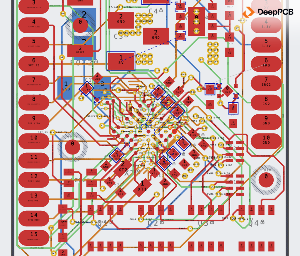

211 of 212 connections complete on 0.1 mm tracks, around the designer’s micro-via BGA fan-out.
Open the routed board in DeepPCB: https://app.deeppcb.ai/shared/i-mCf_jYdgtlhrP95yveM3NFEQPnxsa8Nnttt_oEtt8

A compact 6-layer board built around a SAMD51 microcontroller, with QSPI flash, USB, a battery input and a buck converter module. It has 65 nets and 212 connections, routed on 0.1 mm tracks. It’s one of the three boards Zach Peterson’s community sent us for our episode of Altium’s OnTrack podcast, and the tightest of them.
The board isn’t ours, so we’re not sharing the design file. The link above opens our routed result.
The result at a glance
Routed in July 2026 by our engineer, on the board as submitted apart from the changes listed below.
| RESULT | |
|---|---|
| Connections complete | 211 of 212 (99.5%) |
| Already connected at import | 136, through the copper the designer left in place |
| First reached 210 | 1 h 25 min 9 s (revision 124) |
| Reached 211 | 1 h 50 min 54 s (revision 132) |
| Vias | 190, including the designer’s 148 |
| Total track length | 687.67 mm, including the designer’s 122.71 mm |
| By hand, our engineer’s estimate | 56 hours (7 working days), our engineer’s estimate |
| Review and cleanup our result still needs | 16 hours, our engineer’s estimate |
Left to run longer, it gets the last one too: the same run reached 212 of 212 at revision 133, after 6 h 11 min 7 s.
What we changed before the run
- We kept three things the designer did by hand: the USB pair, the power-supply vias and the BGA fan-out, which is built on micro-vias. We deleted the rest of the tracks and vias, so 148 of the designer’s vias stayed. The planes on the GND and PWR layers stayed in place too.
- The board has two width rules. We lowered the default from 0.254 mm to 0.1 mm and the power rule from 0.381 mm to 0.102 mm. DeepPCB takes a single preferred width from each Altium width rule, so those are the widths it routes at. We also cut the vias to one type, a 0.4 mm pad with a 0.2 mm hole.

What Cooper set up
- The GND and PWR layers carry the ground and split power planes, but both were typed as signal. Cooper set them to power.
- The USB D+ and D- lines weren’t defined as a pair. Cooper created the pair at 0.2 mm with a 0.15 mm gap.
- It also proposed widening the power nets to 0.5 mm. That change was not applied on this run, so the power tracks stayed at 0.102 mm.

What we didn’t do
- We didn’t build the BGA fan-out or route the USB pair. At the time of the run the router didn’t place micro-vias or route short differential pairs well, so we kept the designer’s.
- On import, DeepPCB set aside ten of the board’s clearance rules and the object-type clearances in an eleventh, because it doesn’t read how they’re scoped yet, along with the cutout regions and two copper-fill restrictions. The net-class clearance, 0.102 mm, applies instead.
- It isn’t a finished board. Our engineer estimates 16 hours of manual cleanup to finish it, twice the other two boards. The estimate for routing it by hand covers the whole board, including the parts the designer had already done.
Watch the episode
This board was one of the three sent in for our episode of Altium’s OnTrack with Zach Peterson.
Watch: https://www.youtube.com/watch?v=apvE_ElRhiA
Listen: https://podcast.altium.com/e/ai-pcb-routing-without-the-epic-fails-inside-deeppcb/
More on the episode: https://deeppcb.ai/natural-language-pcb-routing/